


1. Pneumatic Ship Fender Introduction
Pneumatic rubber fenders are widely used in oil tank, cargo ship, yacht, offshore platform, big shipyard, military harbors, huge bridge piers.
Compared to traditional solid rubber fender, pneumatic has following advantages
1. Big energy/ impact absorption capacity, small reaction force to ships
2. Easy and fast installation
3. Higher elasticity. It doesn’t get deformation under compression
4. Light weight
5. Economical and practical
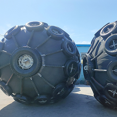

there are many type of Pneumatic Ship Fender with various functions based on different protective jacket and design.
Henger could provide OEM service and technical design based on customer requirement and actual demand. contact our sales service for more details.
Initial internal pressure:
1.Pneumatic fender 50 (initial internal pressure 50 KPa)
2.Pneumatic fender 80 (initial internal pressure 80 KPa)


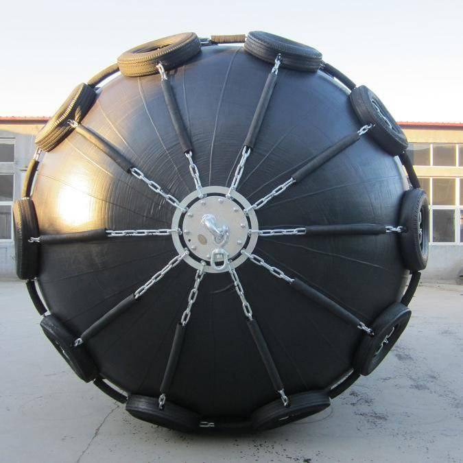
1)Outer rubber layer
Rubber layer that covers the outside of the fender to protect the cord layers and the inner liner rubber from
abrasion and other external forces.
2)Inner rubber layer
liner of a rubber membrane that seals the pressurized air inside the fender.(In general,we will make some inner
rubber container in advance and inflate them.few days later,we will test the pressure again.The one which it's
pressure did not change is good one.We will put it into store and when clients order we can use it directly.
This can ensure every fender we send to client is airtight one)
3)Synthetic-tyre-cord layer for reinforcement layer
layer made of synthetic-tyre-cord fabric which maintains the internal air pressure of the fender.
4)Flange opening
which is mounted on the fender to which an air valve can be adapted.(our flange are all
Embedded welding, very stable)
5)Initial internal pressure
Air pressure at which an uncompressed fender operates.

In recent years,there is a new upsurge of wharf and port building. Because of the super large ships,the berthing collision energy is multiplied. Due to the low energy absorption and large reaction force of previous rubber fenders at the wharfs, The ship side and docks usually may be damaged. The low compression reaction force property of pneumatic rubber fender conforms to the dock construction light-weighting trend and protects the ship side from damage as well. Therefore,Our Pneumatic rubber fender are widely used in large-scale docks,wharves and offshore platforms.


Our manufactures Pneumatic Rubber Fenders in a wide range of sizes. We can offer sizes from 0.5m diameter and 1m length up to 4.5m diameter and 12m length. The Florescence series comes with or without chain and tire netting made of used truck tires (aircraft tires are optional).
Pneumatic Rubber Fenders are manufactured and tested in accordance with ISO 17357:2014. This is the only standard ensuring the high quality of fenders. Our fenders are suitable for all marine conditions and built to withstand the harsh forces involved in STS and STD operations.
Florescence manufactures Pneumatic Rubber Fenders in a wide range of sizes. We can offer sizes from 0.5m diameter and 1m length up to 4.5m diameter and 12m length. The Florescence series comes with or without chain and tire netting made of used truck tires (aircraft tires are optional).
Florescence Pneumatic Rubber Fenders are manufactured and tested in accordance with ISO 17357:2014. This is the only standard ensuring the high quality of fenders. Our fenders are suitable for all marine conditions and built to withstand the harsh forces involved in STS and STD operations.
Florescence series fenders can be delivered with class certification (BV/CCS/ABS/DNV etc.).

50Kpa | 80Kpa | |||||
Nominal size | Guaranteed energy absoprtion | Reaction force at GEA deflection | Hull pressure at GEA deflection | Guaranteed energy absoprtion | Reaction force at GEA deflection | Hull pressure at GEA deflection |
(mm) | (kNm) | (KN) | (kPa) | (kNm) | (KN) | (kPa) |
500×1000 | 6 | 64 | 132 | 8 | 85 | 174 |
600×1000 | 8 | 74 | 126 | 11 | 98 | 166 |
700×1500 | 17 | 137 | 135 | 24 | 180 | 177 |
1000×1500 | 32 | 182 | 122 | 45 | 239 | 160 |
1000×2000 | 45 | 257 | 132 | 63 | 338 | 174 |
1200×2000 | 63 | 297 | 126 | 88 | 390 | 166 |
1350×2500 | 102 | 427 | 130 | 142 | 561 | 170 |
1500×3000 | 153 | 579 | 132 | 214 | 761 | 174 |
1700×3000 | 191 | 639 | 128 | 267 | 840 | 168 |
2000×3500 | 308 | 875 | 128 | 430 | 1150 | 168 |
2500×5000 | 663 | 1381 | 137 | 925 | 1815 | 180 |
2500×5500 | 943 | 2019 | 148 | 1317 | 2653 | 195 |
3300×4500 | 1175 | 1884 | 130 | 1640 | 2476 | 171 |
3300×6500 | 1814 | 3015 | 146 | 2532 | 3961 | 191 |